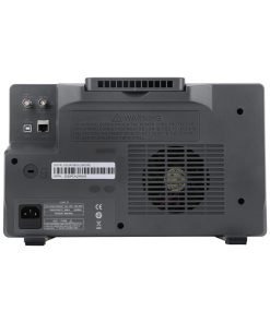
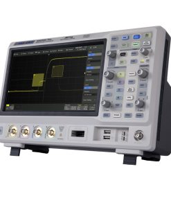
OVERVIEW
Excellent Operability
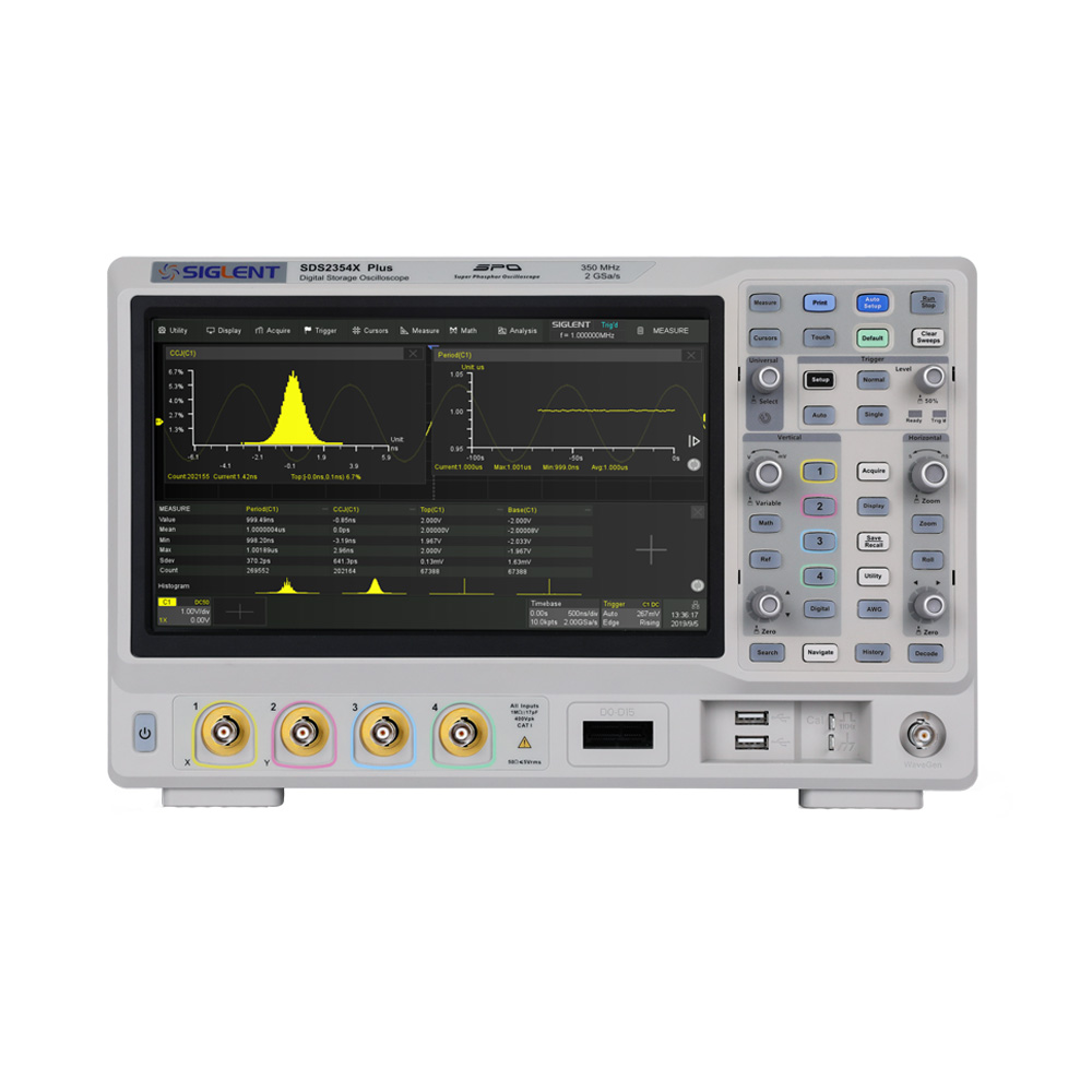
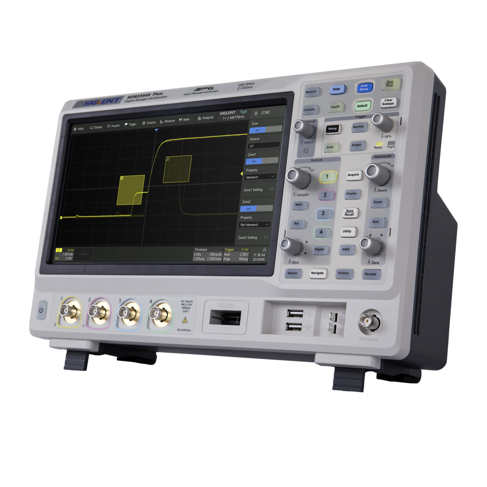
· 10.1” display with 1024×600 resolution
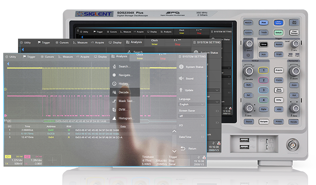
· Capacitive touch screen, supports multi-touch gestures, traces can be moved or scaled efficiently by a finger touch
· Built-in web server supports remote control over the LAN port using a web browser
· External mouse and keyboard support
Provides Higher Resolution and Lower Noise
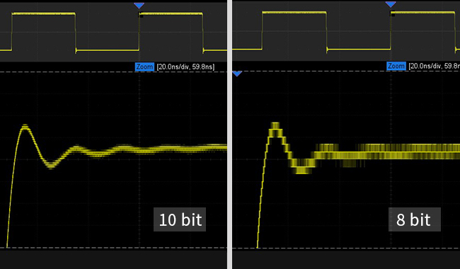
10-bit mode combined with Zoom shows you more details and less noise on the waveform.
The vertical and horizontal zoom feature of the SDS2000X Plus enable the user to pick a region and magnify the captured signal in order to conduct a more detailed analysis. Vertical zoom has an added advantage: The original vertical settings remain unchanged and the input stage won’t be overdriven. This means you can view more details of the waveform with minimal distortion.
Power Loop Response Analysis (Bode Plot)
Stability is a very important indicator in power supply design. In general, stability measurement requires a special frequency response analyzer, but it is very expensive. Siglent offers an affordable solution: SDS2000X Plus oscilloscope and signal source Power loop measurement with standard Free Bode Plot II software.
· Higher measurement sensitivity and accuracy
· Variable excitation scan mode allowed for complex test scenarios of the power control loop test box
· User-friendly UI design
· List and cursor measurements, more intuitive

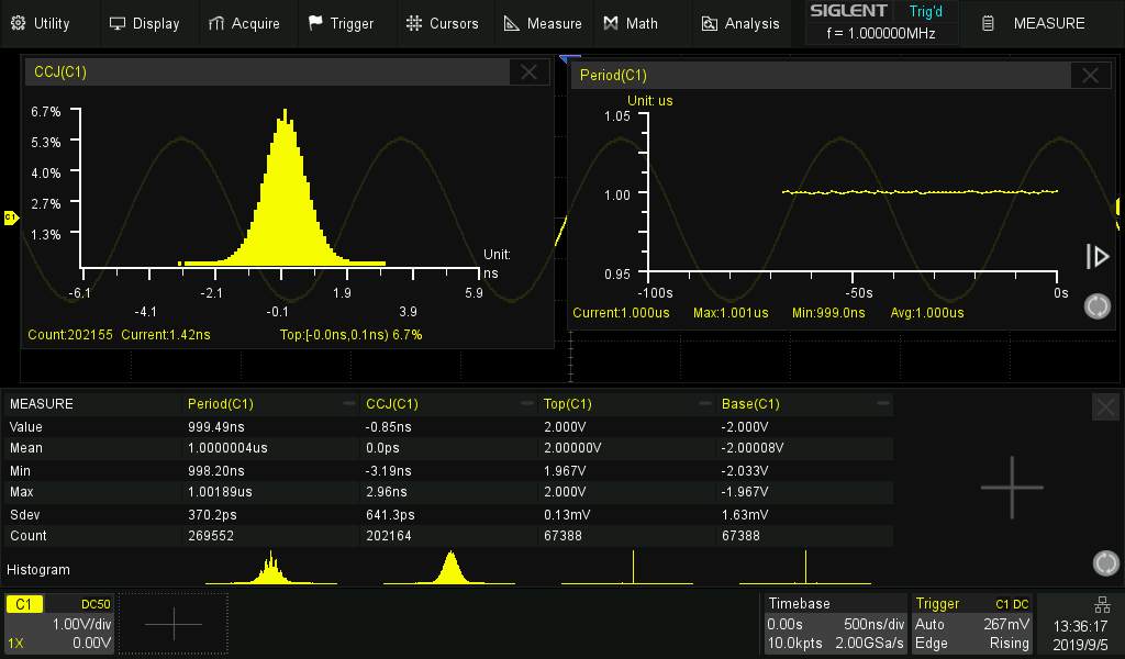
Measurements for Parameters and Parameter Statistics
Parameter measurements includes 4 categories: horizontal, vertical, miscellaneous and channel delay providing a total of 50+ different types of measurements. Measurements can be performed within a specified gate period. Measurements on Math, Reference and History frames are supported.
Statistics shows the current value, maximum value, minimum value, standard deviation and mean value of up to 12 parameters simultaneously. Histogram is available to show the probability distribution of a parameter. Trend is available to show the parameter value vs. time. In addition, horizontal measurements can process up to 1000 signal edges within one single frame, thus greatly improving the test efficiency.
Specifications
| Bandwidth | 100 MHz, 200 MHz, 350MHz(upgradable to 500 MHz) |
| Sample Rate(Max.) | 2 GSa/s |
| Waveform Capture rate(Max.) | 500,000 wfm/s |
| Analog Channels | 2/4 + EXT |
| Trigger Type | Edge, Slope, Pulse, Window, Runt, Interval, Dropout, Pattern, Video and Serial |
| Serial Trigger and decode | Standard: I2C, SPI, UART/RS232, CAN, LIN Optional: CAN FD, FlexRay, I2S, MIL-STD-1553B |
| Math | 2 traces 2 Mpts FFT, +, -, x, ÷, d/dt, ∫dt, √, average, ERES, and formula editor |
| Measurement | More than 50 parameters,supports statistics with histogram and trend |
| Data processing and analysis tools | Search, Navigate, History, Mask test, Bode plot, Power Analysis (optional) and Counter |
| Digital channel (optional) | 16-channel; maximum sample rate up to 500 MSa/s; record length up to 50 Mpts/ch |
| Waveform Generator (optional) | Single channel, frequency up to 50 MHz, 125 MSa/s sample rate, 16 kpts waveform memory |
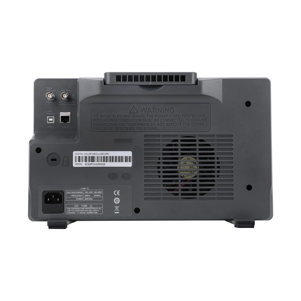
| Interface | USB 2.0 Host x2, USB 2.0 Device, LAN, External trigger, Auxiliary output (TRIG OUT,PASS/FAIL) |
| Probe(standard) | SP2035A, 350 MHz, 1 probe supplied for each channel PP215, 200 MHz, 1 probe supplied for each channel |
| Display | 10.1” TFT LCD with capacitive touch screen(1024*600) |

